Monday, November 4, 2013

Setting the Correct Date/Time on a BeagleBone Black

I got tired to typing in
ntpdate -b pool.ntp.org
everytime I rebooted my BeagleBone Black. So, I searched around and found the following command will automatically set the correct time/date after every boot.
/usr/lib/connman/test/set-global-timeservers pool.ntp.org
I'm also collecting these tips on this page: http://exadler.myshopify.com/pages/beaglebone-black-useful-tips.

Wednesday, October 30, 2013

Building more DMCC's (Dual Motor Controller Capes).

We were running low on our inventory of DMCC Mk.6 (Dual Motor Controller Capes), so I had to take some time to build them.  I'm now using the stencil cutting technique from
http://dangerousprototypes.com/forum/viewtopic.php?f=68&t=5341 on my Silhouette Cameo cutter http://www.silhouetteamerica.com/select-a-silhouette.  The results are much better with the gerber2graphtec code from https://github.com/pmonta/gerber2graphtec.  

Anyways, here's a fun picture of a Beaglebone Black surrounded by DMCC's:

Beaglebone Black Surrounded!

Saturday, October 19, 2013

BeagleBone GPIO in C for iGaging DRO

I'm currently trying to build a DRO interface to iGaging scales based on Yuriy's work : http://www.yuriystoys.com/p/android-dro.html.  As a first step, I have to duplicate the signal pulses from the iGaging controller using the BeagleBone Black GPIOs.

I scoped out my iGaging controller and found that it is providing clock pulses of 24uSec pulse width with a duty cycle of 128uSec.  The iGaging protocol is basically a synchronous clock read only protocol with 21 bits.

After Google'ing many, many sites, (and no, I can't use Python, as I need microsecond level control of the pulses, Python would definitely be too slow), I found some sites that recommend using buffered writes (fopen/fwrite).  Attempting that at first led me down an unreliable path.  I eventually changed the write methods to use low level unix i/o (open/write), and that gave me much better results.

Here are some oscilloscope screenshots showing multiple runs of the code.  Note that there is a random variable pulse delay that occurs on occasion.  That's probably something going on in the Linux O/S (which is why Linux is not meant to be a real time operating system!).  I'll eventually rewrite the code to use the BeagleBone's PRU (Programmable Realtime Unit - http://processors.wiki.ti.com/index.php/Programmable_Realtime_Unit ) but I'm going to see if the iGaging scales will work even with the extra pulse delay.

10 Pulses correctly spaced

Random delay before last pulse

Delay on the high portion of the 2nd pulse

Delay in the middle of the pulse train


Here's the code I'm using right now to test (feel free to use it as a basis for your GPIO code):
 //  
 // BB-DRO.c - Read iGaging Scales on a BeagleBone Black  
 //  
 // Copyright (C) 2013, Exadler Technologies Inc.  
 // http://www.exadler.com  
 //  
 // Based on a similar work (ArduinoDRO_V2_2) by Yuriy Krushelnytskiy  
 // http://www.yuriystoys.com  
 //  
 // This code is is licensed under   
 // Creative Commons Attribution-ShareAlike 3.0 Unported License.   
 //   
 //  
 //  
 #include <fcntl.h>  
 #include <unistd.h>  
 #include <stdio.h>  
 #include <stdlib.h>  
 #include <string.h>  
 //  
 // Setup GPIO and return a unix file descriptor handle to  
 // that GPIO. The user must close that file descriptor when finished  
 //   
 int setupGPIO(char *pszGPIO, char *pszDir)  
 {  
   int fd;  
   int len;  
   int result;  
   char buf[120];  
   if (pszGPIO == NULL) {  
     printf("Error: pszGPIO is NULL!\n");  
     exit(1);  
   }  
   if (pszDir == NULL) {  
     printf("Error: pszDir is NULL!\n");  
     exit(1);  
   }  
   if ((strcmp(pszDir,"in") != 0) && (strcmp(pszDir,"out") != 0)) {  
     printf("Error: pszDir must be either 'in' or 'out'\n");  
     exit(1);  
   }  
   len = strlen(pszGPIO);  
   if ((len < 1) || (len > 40)) {  
     printf("Error: pszGPIO = %s is too long or too short\n",pszGPIO);  
     exit(1);  
   }  
   // First enable GPIO30  
   fd = open("/sys/class/gpio/export",O_WRONLY | O_APPEND);  
   if (fd == -1) {  
     printf("Cannot open /sys/class/gpio/export to setup GPIO\n");  
     exit(1);  
   }  
   result = write( fd, pszGPIO, len );  
   if (result != len) {  
     printf("Cannot write to /sys/class/gpio/export to setup GPIO %s\n",pszGPIO);  
     printf("Wrote %d bytes\n",result);  
     close(fd);  
     // Remove exiting here for now  
     // as it will fail if the GPIO was already exported  
     // so just ignore the error  
 //    exit(1);  
   }  
   close(fd);  
   // Now set GPIO 30 direction to output  
   sprintf(buf, "/sys/class/gpio/gpio%s/direction", pszGPIO);  
   fd = open(buf,O_WRONLY);  
   if (fd == -1) {  
     printf("Cannot open %s to setup GPIO\n",buf);  
     exit(1);  
   }  
   result = write( fd, pszDir, strlen(pszDir) );  
   if (result != strlen(pszDir)) {  
     printf("Cannot write to %s setup GPIO\n", buf);  
     close(fd);  
     exit(1);  
   }  
   close(fd);    
   // Now open the GPIO value for writing  
   sprintf(buf, "/sys/class/gpio/gpio%s/value", pszGPIO);  
   fd = open(buf,O_WRONLY);  
   if (fd == -1) {  
     printf("Cannot open %s to write to the GPIO\n", buf);  
     exit(1);  
   }  
   return fd;  
 }  
 //  
 // freeGPIO - release the GPIO port  
 //   
 void freeGPIO(char *pszGPIO)  
 {  
   int fd;  
   int len;  
   int result;  
   if (pszGPIO == NULL) {  
     printf("Error: pszGPIO is NULL!\n");  
     exit(1);  
   }  
   // unexport the GPIO  
   // First open the unexport file  
   fd = open("/sys/class/gpio/unexport",O_WRONLY );  
   if (fd == -1) {  
     printf("Cannot open /sys/class/gpio/unexport to free GPIO\n");  
     exit(1);  
   }  
   len = strlen(pszGPIO);  
   result = write( fd, pszGPIO, len );  
   if (result != len) {  
     printf("Cannot write to /sys/class/gpio/unexport to setup GPIO %s\n",pszGPIO);  
     printf("Wrote %d bytes\n",result);  
     close(fd);  
     // Remove exiting here for now  
     // as it will fail if the GPIO was already exported  
     // so just ignore the error  
 //    exit(1);  
   }  
   close(fd);  
 }  
 inline void tickTock(int fd)  
 {  
   int result;  
   int j;  
   if (fd == -1) {  
     printf("Error: tickTock called with bad fd\n");  
     exit(1);  
   }  
   for (j=0;j<1000;j++) ;  
   result = write( fd, "1" , 1);  
   if (result != 1) {  
     printf("Cannot write to fd to set GPIO\n");  
     close(fd);  
     exit(1);  
   }  
   for (j=0;j<1000;j++) ;  
   result = write( fd, "0" , 1);  
   if (result != 1) {  
     printf("Cannot write to fd to set GPIO\n");  
     close(fd);  
     exit(1);  
   }  
 }  
 int main(int argc, char *argv[])  
 {  
   int fd30;  
   // First enable GPIO30  
   fd30 = setupGPIO("30","out");  
   int i;  
   for (i=0; i < 10; i++) {  
     tickTock(fd30);  
   }  
   close(fd30);    
 //  freeGPIO("30");  
   return 0;  
 }  


Wednesday, October 16, 2013

Laser Cut CR2032 Battery Holder

I had a number of CR2032 lying around (purchased a bunch from Digikey, and the original container broke), so I quickly made a battery holder for them.  


I created the design using CamBam (http://www.cambam.info/) -- really great CAM software, and it can do really basic CAD as well -- highly recommended.  I then exported the file as a DXF from CamBam, imported the file using Visio 2010, and then printed it as an XPS file (the format recognized by the Full Spectrum Laser software).  Files are available on thingverse at http://www.thingiverse.com/thing:166866.  The whole project took me about 30 minutes to design, CAD/CAM, Laser Cut, tap the holes, and make, and about 2 hours to take a few pictures, upload it to thingverse, and blog about it.  Whew... talk about documentation taking longer than it does to make it!

Tuesday, October 15, 2013

BeagleBone Black controlling a motor with Python

Finally got the preliminary Python interface done to the DMCC (Dual Motor Controller Cape).  Here's a quick YouTube video on how to use it.  


The DMCC open source schematics can be found at https://github.com/Exadler/DualMotorControlCape.

The DMCC Library can be found at https://github.com/Exadler/DMCC_Library

The DMCC boards can be bought at http://exadler.myshopify.com


Sunday, October 13, 2013

Building a Python interface to C for the Beaglebone Black

Making Python talk to a C library on the Beaglebone Black

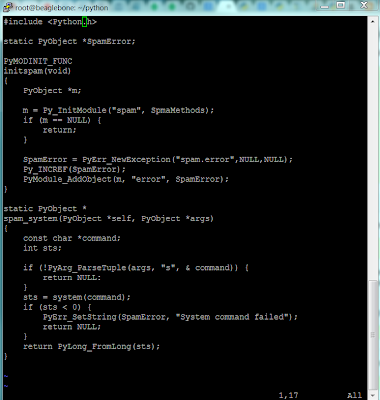
Since we have a working DMCC (Dual Motor Controller Cape) Library in C (see our github repository at  https://github.com/Exadler/DMCC_Library), now the hard part begins... getting Python to work with it.

Disclaimer: I'm new to Python, and although I have extensive C and C++ experience, this will be a learning exercise for me, so if I make any obvious mistakes, please, please, comment and point me in the right direction!

First step was to hit the python docs returned from a Google search:  http://docs.python.org/2/extending/extending.html, and ok, good, the first bullet point is "1.1. A Simple Example".

After reading through the "Simple" example, I'm now really confused.  The Intermezzo on Errors and Exceptions threw me off -- Do I, or don't I have to deal with Errors and Exceptions immediately before I can successfully compile a Python extension in C??  After deciding that I should handle the errors, I cut and paste the code from the Intermezzo section 1.2. into my Beaglebone, only to find in Section 1.3. Back to the Example, they don't have the error handling code!!  Ok, great, silly detour.


Detour of Simple Example from Python C extension

Fine, keep going.  I get down to section "1.4. The Module's Method Table and Initialization Function".  Ok, we have to put in a table of commands -- but where??  Do I put it in a separate file, and there is a main() function?!  I thought I was building a library extension, why is there a main?  Also, how do I install it in the system?? I'm confused?!!

Note: I decided to write this blog entry as I'm learning the system, because I am finding it very confusing, and hopefully this will help the next person that is just as confused as I am!

Ok, Google time!  Searching the web, I get several hits talking about using SWIG, Boost.Python, pyrex, and ctypes.  From this stackoverflow.com posting (http://stackoverflow.com/questions/145270/calling-c-c-from-python), ctypes look simple enough, and there's the compilation steps!!  

ctypes and python with steps!
Ok, try typing in the sample code.  I understand enough C++ that this actually makes sense to me.  So, I'm thinking, this should be a breeze... Everything compiles and then... BAM!  When I get to the steps in python to call the library:

from ctypes import cdll
lib = cdll.LoadLibrary('./libfoo.so')
I get the following error:
root@beaglebone:~/python# python
Python 2.7.3 (default, May 29 2013, 21:25:00)[GCC 4.7.3 20130205 (prerelease)] on linux2Type "help", "copyright", "credits" or "license" for more information.
>>> from ctypes import cdllTraceback (most recent call last):  File "<stdin>", line 1, in <module>
ImportError: No module named ctypes
>>>
Just great!!  I don't have ctypes on the Beaglebone black!  Googling the error yields many cryptic pages.  Arrggh!  

Ok, don't panic, just go back and Google some more.  Finally I find this blog entry from Ned Batchelder (http://nedbatchelder.com/text/whirlext.html), and it actually makes sense!  A good step by step guide!  I especially liked his slides titled "It really works".  Perfect!  The only little thing that was a bit confusing about Ned's guide is whether setup.py was a built in function or whether it was the file from the slide "Building it".  I'm assuming that I had to type it in based upon the comments (what threw me off is his comments about "setup.py knows how to do it with simple declarative..", and the fact that the slides seems to have too little code.  Ok, never mind, just create my setup.py and try typing in "python setup.py".  BAM!  Another gotcha!
root@beaglebone:~# python
Python 2.7.3 (default, Apr  3 2013, 21:37:23)[GCC 4.7.3 20130205 (prerelease)] on linux2Type "help", "copyright", "credits" or "license" for more information.
>>> from distutils.core import setup, ExtensionTraceback (most recent call last):  File "<stdin>", line 1, in <module>
ImportError: No module named distutils.core
>>>
Ok, don't panic, just Google it.  Finally found this stackoverflow.com link:  http://stackoverflow.com/questions/3810521/how-to-install-python-distutils, and wow, someone else is also using the Beaglebone black and Angstrom!

Did the opkg update and opkg install python-distutils, and Ned's code worked!  Well, almost -- I got this far:
root@beaglebone:~/python# python setup.py
usage: setup.py [global_opts] cmd1 [cmd1_opts] [cmd2 [cmd2_opts] ...]
   or: setup.py --help [cmd1 cmd2 ...]
   or: setup.py --help-commands
   or: setup.py cmd --help
error: no commands supplied
root@beaglebone:~/python#
Hmm... there's a help?  Let's try it.  First few lines gave me the key:
root@beaglebone:~/python# python setup.py --help
Common commands: (see '--help-commands' for more)
  setup.py build      will build the package underneath 'build/'
  setup.py install    will install the package
...
Let's try the build and install, bingo!  It worked!
root@beaglebone:~/python# python setup.py build
running build
running build_ext
building 'ext1' extension
arm-angstrom-linux-gnueabi-gcc -march=armv7-a -mthumb-interwork -mfloat-abi=softfp -mfpu=neon -mtune=cortex-a8 -D__SOFTFP__ -fno-strict-aliasing -O2 -pipe -g -feliminate-unused-debug-types -DNDEBUG -g -O3 -Wall -Wstrict-prototypes -fPIC -I/usr/include/python2.7 -c ext1.c -o build/temp.linux-armv7l-2.7/ext1.o
arm-angstrom-linux-gnueabi-gcc -march=armv7-a -mthumb-interwork -mfloat-abi=softfp -mfpu=neon -mtune=cortex-a8 -D__SOFTFP__ -shared -Wl,-O1 -Wl,--hash-style=gnu -Wl,--as-needed build/temp.linux-armv7l-2.7/ext1.o -L/usr/lib -lpython2.7 -o build/lib.linux-armv7l-2.7/ext1.so
root@beaglebone:~/python#
root@beaglebone:~/python# python setup.py install
running install
running build
running build_ext
running install_lib
copying build/lib.linux-armv7l-2.7/ext1.so -> /usr/lib/python2.7/site-packages
running install_egg_info
Removing /usr/lib/python2.7/site-packages/UNKNOWN-0.0.0-py2.7.egg-info
Writing /usr/lib/python2.7/site-packages/UNKNOWN-0.0.0-py2.7.egg-info
root@beaglebone:~/python#
Trying to run the extension in the python command line we get
root@beaglebone:~/python# python
Python 2.7.3 (default, May 29 2013, 21:25:00)
[GCC 4.7.3 20130205 (prerelease)] on linux2
Type "help", "copyright", "credits" or "license" for more information.
>>> import ext1
>>> ext1.hello_world()
 hello_world called
'hello, world!'
>>>
Yay!!  I works!!  Ok, enough working on the code for the day, we got the first steps and now I'm calling it a night.  For reference, here is the ext1.c file:
// ext1.c: A sample C extension: one simple function
#include "Python.h"
// hello_world function.
static PyObject *
hello_world(PyObject *self, PyObject *args)
{
    printf(" hello_world called\n");
    return Py_BuildValue("s", "hello, world!");
}
// Module functions table.
static PyMethodDef
module_functions[] = {
    { "hello_world", hello_world, METH_VARARGS, "Say hello." },
    { NULL }
};
// This function is called to initialize the module.
void
initext1(void)
{
    Py_InitModule3("ext1", module_functions, "A minimal module.");
}

Hope this helps someone, because I sure could have used this help many, many, many hours ago!  And, for those python gurus out there, let me know if I'm missing something or if I'm on the right track!  Thanks.


Monday, September 23, 2013

Toronto Maker Faire and New Products

A big thanks to everyone that visited us at the Toronto Maker Faire.  We enjoyed meeting everyone.

Our table at the Toronto Maker Faire

At the Maker Faire, we also brought out a few new products.  First we have our Encoder 5132 - a Quadrature encoder that is pin compatible with the US Digital E4P -  http://www.usdigital.com/products/encoders/incremental/rotary/kit/E4P.  We had originally intended to use the E4P in our robot designs, but a few months ago we tried to order some more E4P's and noticed the following:


The E4P is not recommended for new product development!  Yikes!  So that revelation led us to design and build the Encoder 5132, making sure that it was a pin for pin replacement for the E4P.  You can see more specifications of our encoder at http://exadler.myshopify.com/products/encoder-5132.  The good news is that we are making it for sale for everyone at a much cheaper price than the E4P ($25 vs $40 -- see http://www.andymark.com/product-p/am-0174.htm), and we're throwing in the cable.  The bad news is that it actually takes me a long time to lathe the shaft needed for the Encoder 5132, as I needed to get the tolerances under 0.5mm.  However, now I have an excuse to CNC convert my lathe!!

Quadrature Encoder 5132
For those of you who are unfamiliar with quadrature encoders, they are basically rotation sensors that can tell you how many rotations/degrees the shaft has turned.  They put out a signal on two wires like this:
Signals from quardature encoder with the shaft rotating clockwise
Each pulse is basically one degree of turn.  The reason for having two signals (A and B) is so that you can tell whether the shaft is turning clockwise or counter clockwise by observing which signal is rising first.  Our DMCC Mk.6 board has two Quadrature Encoder inputs that take the signals and count how many degrees the shaft has rotated.  So, with a simple 'C' library call to our DMCC Library you can get the exact position (well, to 1 degree) the shaft has turned, or even the velocity of the shaft.

// -------------------------- 
// Quadrature Encoder Interface (QEI) functions 
// -------------------------- 

// getQEI - Gets the QEI for the desired motor 
//     Prints an error if QEI for motor is not received 
// Parameters:
//     fd - connection to the board (value returned from DMCCstart) 
//     motor - motor number desired 
// Returns: QEI for given motor 
//     always returns 0 if an error occurs 
unsigned int getQEI(int fd, unsigned int motor); 

// getQEIVel - Gets the QEI velocity for the desired motor 
//     Prints an error if QEI velocity for motor is not received 
// Parameters: 
//     fd - connection to the board (value returned from DMCCstart) 
//     motor - motor number desired 
// Returns: QEI velocity for given motor 
//     always returns 0 if an error occurs 
int getQEIVel(int fd, unsigned int motor);


After we got the encoder replacement working, we needed something to showcase at the Toronto Maker Faire, so we built Orbit the robot! (also avaliable in kit form).

Orbit Robot
The top plate, bottom plate, large gears, and small gears are all Laser cut from 1/8" acrylic.  The white vertical pieces are CNC milled Delrin plastic, and the rest of the mechanical parts and motor is from Vex Robotics.  We added in a Beaglebone Black and our DMCC Mk.6 Dual Motor Controller Cape, and voila! - Instant Robot.

We had sold our assembled Orbit Robot on the first day of the show, so we were scrambling to quickly build another demo robot.  It was a lot harder to build when we realized we forgot to bring the proper screwdriver (small phillips) to the show!

Building a new Orbit Robot at the Toronto Maker Faire


Wednesday, September 18, 2013


We'll be at the Toronto Maker Faire http://makerfairetoronto.com/, showing our DMCC and a few robots.  We hope to see you there.

Sunday, September 15, 2013

opkg upgrade on a Beaglebone black is officially evil.  Just don't do it.  Bad things happen.  Just flash to the latest image and do an opkg update.  You should be good to go on your Beaglebone black.

Saturday, September 14, 2013

Updating Beaglebone black out of the box using ethernet and ssh seems to run into problems with opkg update; opkg upgrade step.

Steps to reproduce:

  1.  Get a brand new Beaglebone black out of the box
  2. Upgrade the image to the 06-20-2013 image using an MMC card
  3. rebooted Beaglebone connected via Ethernet
  4. ssh'ed into the Beaglebone black
  5. ran "opkg update", everything ok
  6. did "opkg upgrade", things work for a while and then you get
    Downloading http://www.angstrom-distribution.org/feeds/unstable/ipk/glibc/armv7a//Packages.gz.wget: bad address 'www.angstrom-distribution.org'Downloading http://feeds.angstrom-distribution.org/feeds/v2012.12/ipk/eglibc/armv7a-vfp-neon/base/Packages.gz.wget: bad address 'feeds.angstrom-distribution.org'Downloading http://feeds.angstrom-distribution.org/feeds/v2012.12/ipk/eglibc/armv7a-vfp-neon/machine/beaglebone/Packages.gz.wget: bad address 'feeds.angstrom-distribution.org'Downloading http://feeds.angstrom-distribution.org/feeds/v2012.12/ipk/eglibc/armv7a-vfp-neon/debug/Packages.gz.wget: bad address 'feeds.angstrom-distribution.org'
    ...
Steps to fix:

My quick hack is to edit /etc/hosts and add in the IP address of feeds.angstrom-distribution.org
140.211.169.179 feeds.angstrom-distribution.org
So, my /etc/hosts file now looks like

root@beaglebone:~# cd /etc
root@beaglebone:/etc# vi hosts
root@beaglebone:/etc# cat hosts
127.0.0.1       localhost.localdomain           localhost
140.211.169.179 feeds.angstrom-distribution.org
127.0.0.1 beaglebone
root@beaglebone:/etc#
Now, opkg upgrade seems to work fine.

Please note that this is a HACK.  Please remove the line from your /etc/hosts after the upgrade is done.

UPDATE:

The upgrade finished, but had lots of errors of not enough space, and then it dropped the ssh connection.  Rebooting it and attempting to restart opkg upgrade fails.

I'm beginning to think the correct way is to avoid opkg upgrade, or as http://www.circuidipity.com/getting-started-with-beaglebone-black.html put it:

'opkg upgrade'

Fix: Do not run this command or else Bad Things Will Happen.


Thursday, September 12, 2013


First few boards have been built.  Calling it a night and building more tomorrow.
Our web store is now launched at https://exadler.myshopify.com, where you can actually buy the Dual Motor Controller Capes (DMCC Mk.6).


Wednesday, September 11, 2013

100 DMCC Mk.6 Boards
Got another shipment of DMCC Mk.6 blank boards.  Time to start assembling them!

Our store is also open now at https://exadler.myshopify.com if you want to buy one of these assembled boards.


Thursday, July 25, 2013

DMCC Mk.5 does LED Lights!!

We do lights!!  Here we have two banks of LED lights controlled by the DMCC Mk.5 turning on and off using a PWM control program on the Beaglebone black.


We were prompted to do this quick breadboard wiring when someone asked us if we could control a long string of LED lights.  Our estimate based upon the current draw from this circuit is that we could control 800 LEDs (two sets of 400 LEDs) on a single DMCC (Dual Motor Controller Cape) board.

Wednesday, July 10, 2013

The Mark 5 DMCC (Dual Motor Controller Cape) has been built!  We are hoping to be able to sell these boards at the Toronto Maker Faire (http://makerfairetoronto.com) on September 21-22.

DMCC Mk.5 working!
(CR2032 coin cell left in picture accidentally - not used on board)

Here are the details on the connections of the board:


  • Quadrature Encoder Inputs 1 and 2:
  • Cape ID Selector:
    • Used to select a different cape ID for stacking up to 4 capes on the same Beaglebone black
  • Motor Power LED:
    • Indicates that there is power from the Motor Power Connector.  The motors are powered from the Motor Power Connector instead of the Beaglebone black.  This allows the DMCC (Dual Motor Controller Cape) to power motors of a different voltage rating (up to +28V DC)
  • Motor 1 and 2 LED:
    • These LEDs are dark (off) when the motors are not being powered.  They light up GREEN when the motors are powered in forward motion, and they light up RED when the motors are powered in reverse motion.
  • Motor 1 and 2 Connectors:
  • Motor Power Connector:
    • This is the input power that powers the motors.  A four pin Micro-Fit connector was used to provide the current required for driving two motors.

Here is a video showing the DMCC Mk.5 working:

DMCC Mk. 5


Wednesday, June 5, 2013

Dual Motor Cape Version 4 is in!!


I'm using the Silhouette Cameo Stencil cutting technique I found from http://www.idleloop.com/robotics/stencil/index.php.  The results were good enough to use:
Minor variations I found was that I had to set the physical cutter depth to 3 instead of 1 as indicated in Cathy Saxon's article.

Populating the board (except for missing J4, still in transit from Mouser):

One of the things you'll notice that I've changed is the motor and power connectors.  I've using Molex Microfit connectors http://www.molex.com/molex/products/family?key=microfit_30&channel=products&chanName=family&pageTitle=Introduction, instead of the screw terminals.  The reason for the change is that I felt that using the screw terminals might be unreliable when using this board on a mobile robot.  The only downside is that the Microfit connectors are rated at 5A max.  I think I will have to leave it at that spec when I sell the boards (although you could always solder wires directly to the board to get a higher current -- the ST Micro HBridge chips are rated for up to 30A if you add a few heat sinks in).  I'll probably keep the spec at 5A continuous, and 10A peak (violating the Microfit spec a bit -- they do spec the two circuit connector at 7A, but I want a little leeway).


Thursday, May 2, 2013

Bringing up a new cape for the Beaglebone Black, i2c-1 is actually I2C2


Dual Motor Controller Cape on top of Beaglebone Black!
I am currently trying to bring up the Dual Motor Controller Cape on the brand new Beaglebone Black, and finding out the gotchas along the way.

First off, when I attempted to find all the i2c interfaces using i2cdetect, I got the following screen:


Where is I2C2 ??  The Beaglebone is supposed to have 3 I2C interfaces, and I2C2 is supposed to be the one connected to the EEPROM of the capes.

Fortunately, with help from panto on the IRC channel (freenode/#beagle), I found out that i2c-1 is actually I2C2.   Executing the command 'i2cdetect -r 1' and monitoring on the scope actually proves that i2c-1 is actually I2C2!


I2C2 SDA and SCLK